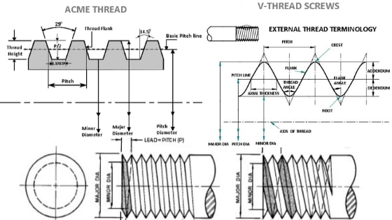
The distance between corresponding points on adjacent thread forms measured parallel to the axis. What the difference is between counterbore and countersink holes.

Gtu Industrial Drafting B E 3 Rd Sem Mechatronics Screw Threads Youtube
In addition some detail is.

. The distance between crest and root measured normal to the axis. The different types of holes used in machining. This makes understanding the drawings simple with little to no personal interpretation.
Screw thread representation present in this chapter is in accordance with the ASME Y146-2001 standard. Figure 35 ISO 128 engineering drawing line type A Figure 35 ISO 128 engineering drawing line type A ISO Type B Line thin straight continuous. ANSI B1201 - NPT - American National Standard Taper Pipe Threads.
Figure 2 - An Isometric Drawing. There are three methods of representing screw threads on a drawing. These are tightened in anticlockwise movement.
Comparison sheet M - BSPP - BSPT - NPT - UNC - UNF Thread Seal Types. One can pack a great deal of information into an isometric drawing. Todays topic is Threads in Engineering Drawing Types of Threads Forms of ThreadsIn this video.
The purpose is to convey all the information necessary for manufacturing a product or a part. These threads are inclined towards the right-hand side. Unified national extra fine.
A thread that when viewed axially winds in a clockwise and receding direction. Different Types of Engineering Drawing Views. The fine threads have tighter manufacturing tolerances than UNC threads and the smaller lead angle allows for finer tension adjustment.
An engineering drawing is a subcategory of technical drawings. Short centre Thread roots Symmetry sign lines. Type A DIMENSIONS NOT COMPLETE large or defnng a a drawng is ted in the Id take if it 22 Dimensioning common features.
This is an overview on how to define screw threads on engineering drawings according to the Unified Inch Screw Thread Standard. Unified national thread note. Threads cut on around.
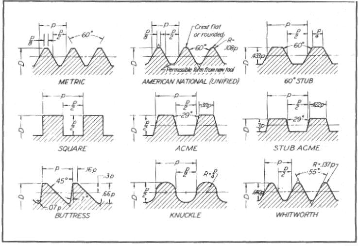
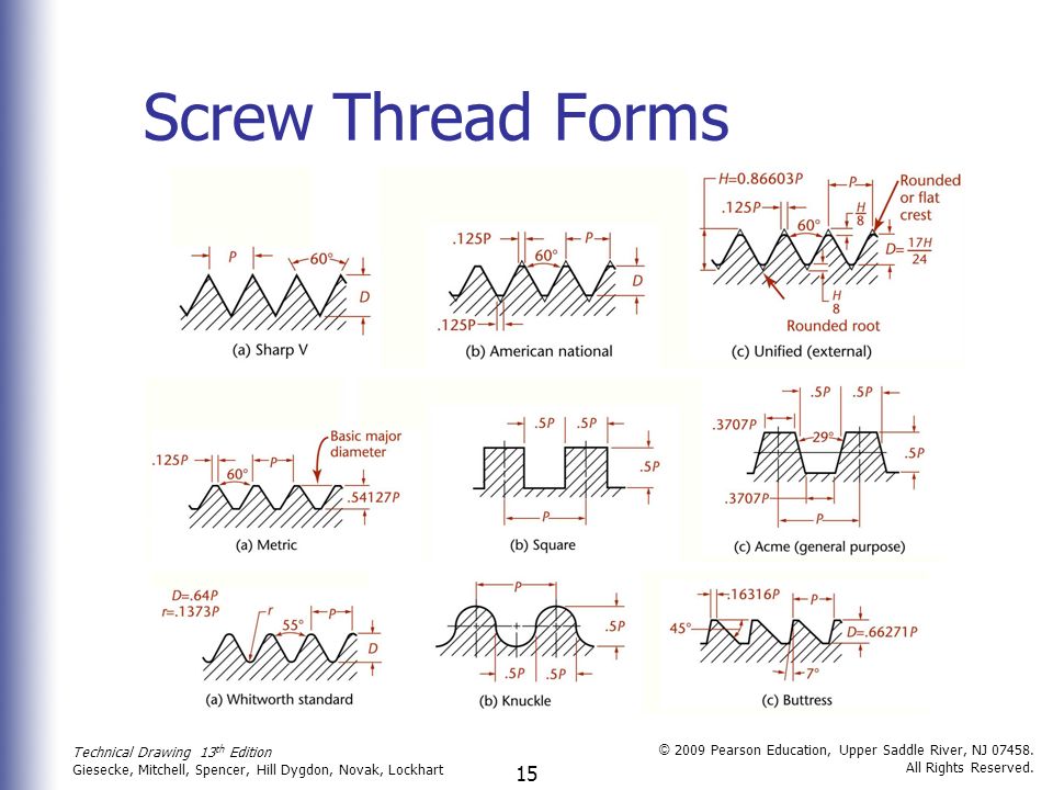
A complete understanding of the object should be possible from the drawing. Engineering Drawing Basics Explained. Type of thread Designation Sample Metric coarse M M16 Metric fine M M16 x 15 Unified screw thread ½ Pipe thread G G14 Pipe taper thread R R14 Trapezoidal thread symetric Tr Tr24x5 Buttres thread S S24x5 Knuckle thread Rd Rd32x18 Left-hand thread LH M16LH Multiple thread P M60x4P3.
Engineering drawings use standardised language and symbols. Any engineering drawing should show everything. If the isometric drawing can show all details and all dimensions on one drawing it is ideal.
A screw thread is a ridge wrapped around a cylinder or cone in the form of a helix with the former being called a straight thread and the latter called a tapered thread. To Add Hole or Thread Notes to a Drawing View On the ribbon click Annotate tab. UNF threads are frequently used in cases where thread engagement is minimized due to thinner wall thickness.
How do you annotate a drawing thread. Note that you should only include a view that contributes to a designs overall understanding. How each type of hole is used in engineering.
NPT and NPTF pipe threads - dimensions according ANSIASME B12013. Unified national thread note components Exercise 3. There are various types of views in an engineering drawing.
23 Screw threads GENERAL REPRESENTATION in 2 24 left-hand of fcr a 12 M 12 2 24a DA 12 rrm_ FIGURE 224. ANSI B1201 - NPS - American National Standard Straight Pipe Threads. This is an overview on how to define screw threads on engineering drawings according to the Unified Inch Screw Thread Standard.
M - ISO thread metric NPT - Pipe thread. Dimensionand Leader Lines Cross Outline of extension lines hatching revolved sections. A thread callout is also inserted if the drawing document is in ANSI standard.
Threads are RH unless otherwise specified. A screw thread often shortened to thread is a helical structure used to convert between rotational and linear movement or force. ANSIASME B15 - ACME Screw Threads.
In addition some detail is. A detailed representation is a close approximation of the appearance of an actual screw thread. A cosmetic thread represents the minor inner diameter of a thread on a boss or the major outer diameter of a thread on a hole and can include a hole callout in drawings.
Isometric drawings show a three-dimensional view of parts. These threads are inclined towards the left hand. So if you want to learn the different types of holes used in engineering youll love todays guide.
These are tightened in a clockwise movement. NPS pressure tight straight pipe threads with lubricant or sealer. GRRp - Whitworth thread BSPPBSPT UNCUNF - Unified National thread.
Figure 36 ISO 128 engineering drawing line type B ISO Type C Line. Types of Threads Right Hand Threads. The symbols used for each hole and how they are shown on engineering drawings.
A screw thread is the essential feature of the screw as a simple machine and. Summary 1 Fasteners 2 Screw Thread Definitions 3 Types of Thread 4 Manufacturing Screw Threads 5 Drawing Screw Threads 6 Unified Threads 7 Metric Threads 8 Drawing Bolts 9 Bolt and Screw Clearances. Screw thread features Exercise 2.
UNEF is a thread finer than UNF and is common to. Each of them serves different purposes. EngineeringDrawing Welcome to TRACKview Channel.
D Cg Lesson 7 Threads Nomenclature Profiles Multi Start Left And Right Hand And Conventional Representation Of Threads

Types Of Threads

Thread Id Made Easy Learn All About Different Types Of Threads
Threads Fasteners And Springs Chapter Technical Drawing 13 Th Edition Giesecke Mitchell Spencer Hill Dygdon Novak Lockhart C 2009 Pearson Ppt Download
13 Types Of Threads How They Work Complete Guide Images

Different Types Of Threads And Their Uses Engineering Choice
13 Types Of Threads How They Work Complete Guide Images

How To Draw Acme Thread Drawing Engineering And Poetry Youtube
0 comments
Post a Comment